10 KiB
[TOC]
1. GPIO概述
GPIO功能分类(P110):
- 输出
- 输入
- 复用
- 时序模拟
GPIO特点(P111):
- 多种工作模式:输入、输出、模拟模式、复用模式;
- 灵活复用:外设的功能与GPIO复用,可以选择是GPIO还是外设;
- 5V电压容限:大部分可以支持5V(芯片核心是3.3V);
- 外部中断
什么是端口(Port)什么是引脚(Pin),P111
2. GPIO电路结构(p112,手册105)
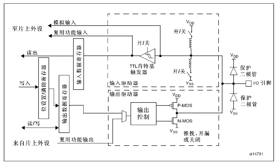
- 端口寄存器组
- 输入输出驱动器
- 输入驱动
- 输出驱动
- 引脚电路
- 保护二极管
- 上拉/下拉电阻
2.1. GPIO工作模式
- 输入模式(作为输入,我们引脚的内阻的高低有不同的用途)
- 浮空输入(电平由外部输入电路决定)
- 上拉输入(初始化电平为高)
- 下拉输入(初始化电平为低)
- 输出模式(一般认为,作为出的引脚,内阻越低越好,为什么?)
- 推挽输出(电平为MCU核心电平)
- 开漏输出(电平可以高于MCU核心电平)
- 模拟模式
- 复用模式
在输入模式下,一定检查引脚的初始化电平,特别是在浮空输入模式下,一定注意引脚的初始化电平!为什么?
2.2. 基于寄存器方式控制GPIO(p115,略)
注意:我们的芯片的端口只有 GPIOA、GPIOB、GPIOC,和书上的芯片不同。
2.2.1. GPIO相关寄存器
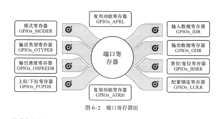
- 模式寄存器:
- 输出类型寄存器:
- 输出速度寄存器:
- 上拉/下拉寄存器:
- 输入数据寄存器:
- 输出数据寄存器:
- 置位/复位寄存器:
- 配置锁定寄存器:书上没有写。
2.2.2. 利用指针访问大哥寄存器(p120略)
每个寄存器都有一个地址,根据芯片手册查询每个寄存器的地址,然后通过读写操作就可以实现相应的功能。
2.3. 基于HAL库方式控制GPIO(P129)
一个芯片上有成千上万个用于控制的寄存器,包括核心功能(时钟、DMA、中断、看门狗、总线速度等),同时也有外设(GPIO、串口、I2C、PWM、定时器、AD等)。如果都是采用寄存器方式的开发,维护起来工作量很大。因此STM32提供了HAL库来简化开发工作,其实就是一系列的宏定义和相关的函数。使得开发者不用再去查询每个寄存器的具体地址和复杂的读写配置工作。
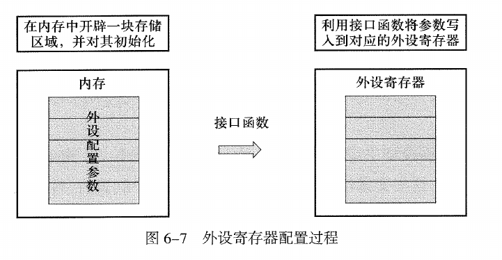
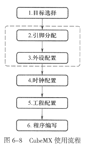
如上图所示,外设的配置过程是先对外设的寄存器进行结构化抽象(在内存中的结构体),然后通过接口哦函数结合结构体对外设的具体寄存器进行操作。这样的操作简化了开发。
想一想,HAL的优势是简化了外设的操作,那么劣势是什么?
一般GPIO需要先对PIN进行初始化,这个步骤在 Stm32CubeMX 中通过配置完成,会自动生成相应的初始化代码;另外就是GPIO引脚的操作,主要是读取和写入操作。
2.3.1. GPIO 外设数据类型(p130)
2.3.1.1. 引脚初始和(GPIO_InitTypeDef)
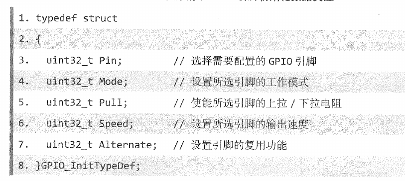
typedef struct
{
  uint32_t Pin;       /*!< Specifies the GPIO pins to be configured.
                           This parameter can be any value of @ref GPIO_pins_define */
  uint32_t Mode;      /*!< Specifies the operating mode for the selected pins.
                           This parameter can be a value of @ref GPIO_mode_define */
  uint32_t Pull;      /*!< Specifies the Pull-up or Pull-Down activation for the selected pins.
                           This parameter can be a value of @ref GPIO_pull_define */
  uint32_t Speed;     /*!< Specifies the speed for the selected pins.
                           This parameter can be a value of @ref GPIO_speed_define */
} GPIO_InitTypeDef;
2.3.1.2. 引脚电平状态(GPIO_PinState)
typedef enum
{
  GPIO_PIN_RESET = 0u,
  GPIO_PIN_SET
} GPIO_PinState;
2.3.1.3. 引脚端口(GPIO_Port)
#define GPIOA               ((GPIO_TypeDef *)GPIOA_BASE)
#define GPIOB               ((GPIO_TypeDef *)GPIOB_BASE)
#define GPIOC               ((GPIO_TypeDef *)GPIOC_BASE)
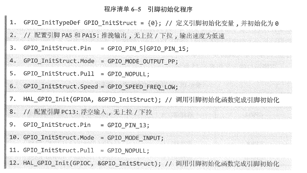
2.3.1.4. 如何初始化(LED的程序为例,和p134差不多)
  #define LED_Pin GPIO_PIN_6
  #define LED_GPIO_Port GPIOA

  GPIO_InitTypeDef GPIO_InitStruct = {0};

  /*Configure GPIO pin : LED_Pin */
  GPIO_InitStruct.Pin = LED_Pin;
  GPIO_InitStruct.Mode = GPIO_MODE_OUTPUT_PP;
  GPIO_InitStruct.Pull = GPIO_NOPULL;
  GPIO_InitStruct.Speed = GPIO_SPEED_FREQ_LOW;
  HAL_GPIO_Init(LED_GPIO_Port, &GPIO_InitStruct);
注意,书上是同时初始化多个端口!请仔细对比一下。
2.3.2. GPIO外设的接口函数(p135)
针对不同的MCU,其GPIOx的取值是不同的。
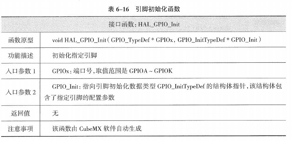
2.3.2.1. 引脚初始化函数(HAL_GPIO_Init)
2.3.2.2. 引脚读取函数(HAL_GPIO_ReadPin)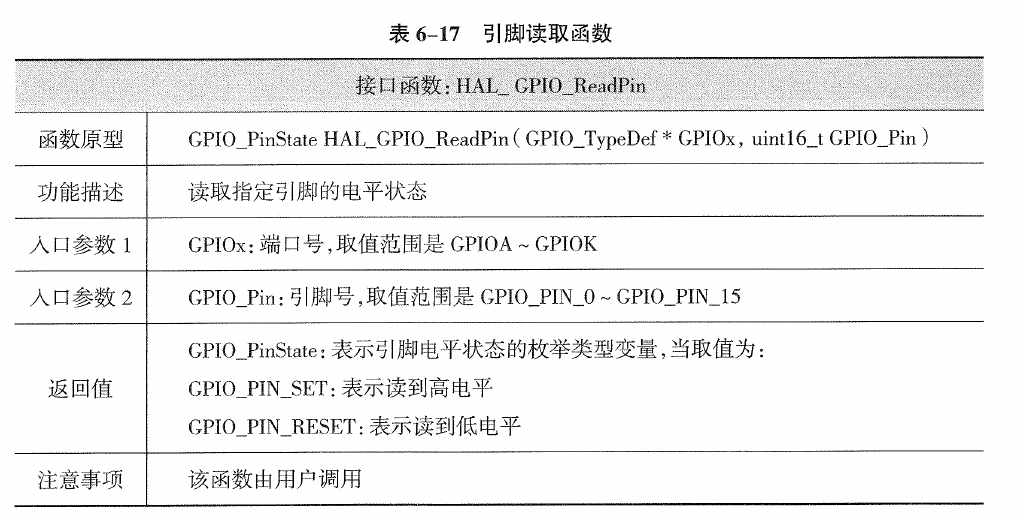
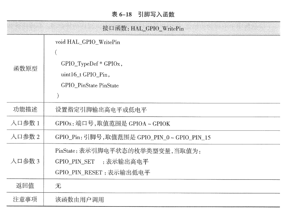
2.3.2.3. 引脚写入函数(HAL_GPIO_WritePin)
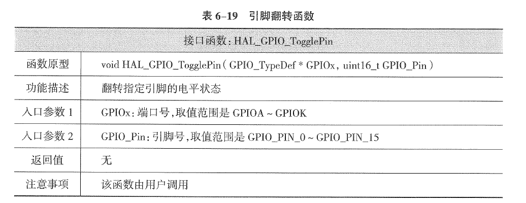
2.3.2.4. 引脚反转函数(HAL_GPIO_TogglePin)
2.3.3. GPIO外色的接口函数源码分析(p136)
GPIO的寄存器定义结构体
typedef struct
{
  __IO uint32_t CRL;
  __IO uint32_t CRH;
  __IO uint32_t IDR;		// 输入寄拍存器
  __IO uint32_t ODR;
  __IO uint32_t BSRR;		// 置位/复位寄存器(p119)
  __IO uint32_t BRR;
  __IO uint32_t LCKR;
} GPIO_TypeDef;
2.3.3.1. HAL_GPIO_ReadPin
/**
  * @brief  Reads the specified input port pin.
  * @param  GPIOx: where x can be (A..G depending on device used) to select the GPIO peripheral
  * @param  GPIO_Pin: specifies the port bit to read.
  *         This parameter can be GPIO_PIN_x where x can be (0..15).
  * @retval The input port pin value.
  */
GPIO_PinState HAL_GPIO_ReadPin(GPIO_TypeDef *GPIOx, uint16_t GPIO_Pin)
{
  GPIO_PinState bitstatus;

  /* Check the parameters */
  assert_param(IS_GPIO_PIN(GPIO_Pin));

  if ((GPIOx->IDR & GPIO_Pin) != (uint32_t)GPIO_PIN_RESET)
  {
    bitstatus = GPIO_PIN_SET;
  }
  else
  {
    bitstatus = GPIO_PIN_RESET;
  }
  return bitstatus;
}
2.3.3.2. HAL_GPIO_WritePin
/**
  * @brief  Sets or clears the selected data port bit.
  *
  * @note   This function uses GPIOx_BSRR register to allow atomic read/modify
  *         accesses. In this way, there is no risk of an IRQ occurring between
  *         the read and the modify access.
  *
  * @param  GPIOx: where x can be (A..G depending on device used) to select the GPIO peripheral
  * @param  GPIO_Pin: specifies the port bit to be written.
  *          This parameter can be one of GPIO_PIN_x where x can be (0..15).
  * @param  PinState: specifies the value to be written to the selected bit.
  *          This parameter can be one of the GPIO_PinState enum values:
  *            @arg GPIO_PIN_RESET: to clear the port pin
  *            @arg GPIO_PIN_SET: to set the port pin
  * @retval None
  */
void HAL_GPIO_WritePin(GPIO_TypeDef *GPIOx, uint16_t GPIO_Pin, GPIO_PinState PinState)
{
  /* Check the parameters */
  assert_param(IS_GPIO_PIN(GPIO_Pin));
  assert_param(IS_GPIO_PIN_ACTION(PinState));

  if (PinState != GPIO_PIN_RESET)
  {
    GPIOx->BSRR = GPIO_Pin;
  }
  else
  {
    GPIOx->BSRR = (uint32_t)GPIO_Pin << 16u;
  }
}
以上的例子要注意位操作。常用的位操作有哪些?
3. 任务实践
3.1. 驱动指示灯(p143)
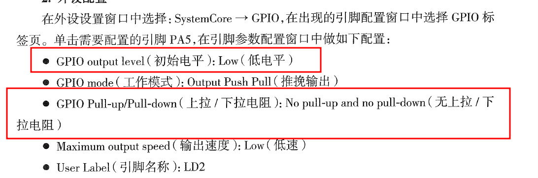
所有的GPIO配置如下图:
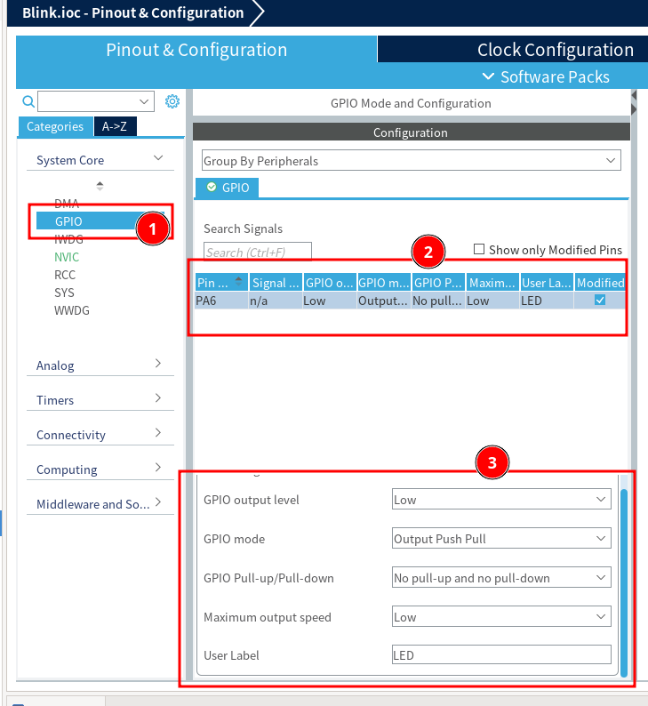
注意:推挽和开漏的区别,这点要结合硬件的设计。
3.2. 按键检测
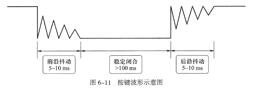
3.2.1. 抖动:
3.2.2. 硬件消抖
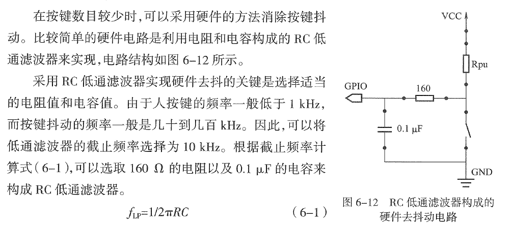
硬件消抖的原理是什么?
看看我们的按钮是否有消抖动的硬件滤波?
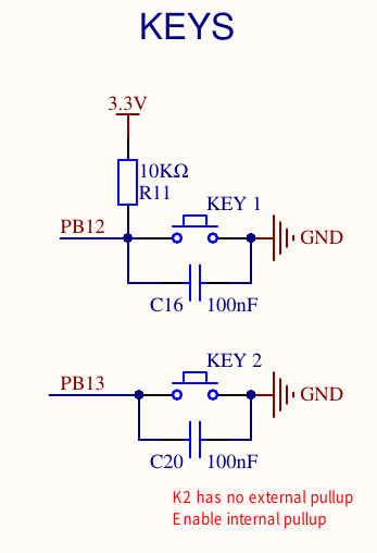
我们的硬件和书上的硬件有什么不同?书上的Rpu作用是什么?
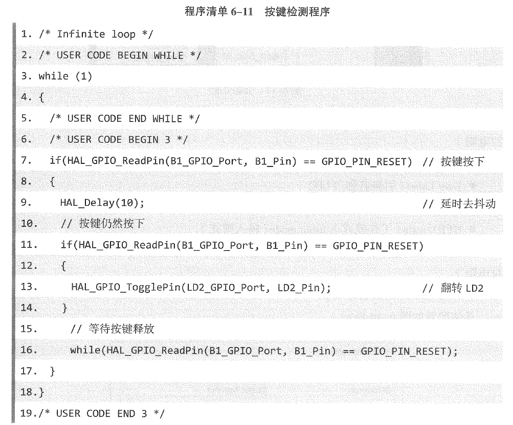
3.2.3. 软件消除抖动
基本原理是什么?
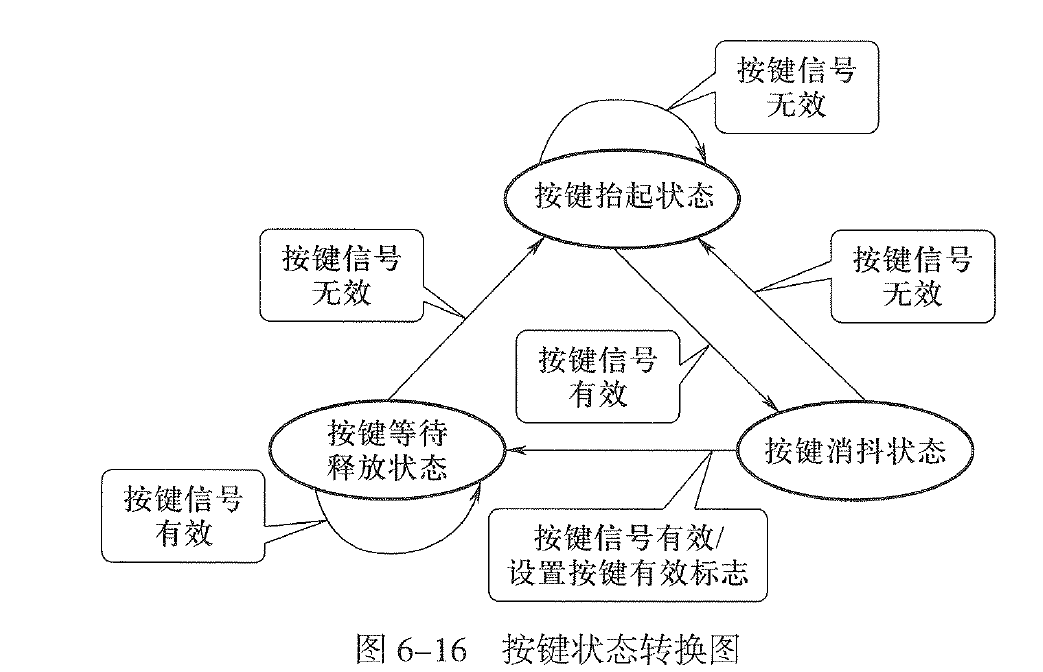
3.3. 利用状态机检测按键(p151 略)
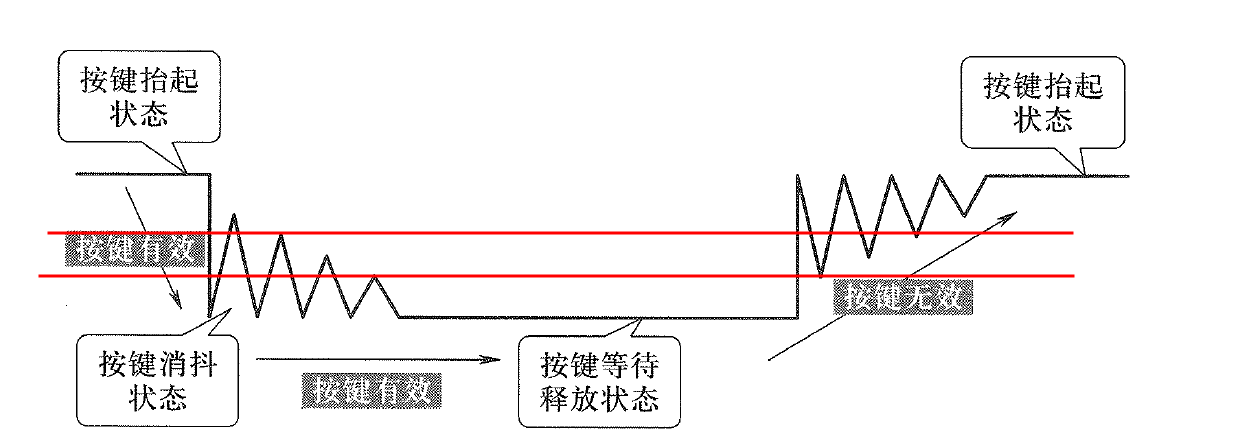
对于输入来说,IO一般不会在输入=VCC的时候判断为高,而是只要超过了一个门限(如2/3 VCC)就判断为高;同理,也不会=GND的时候判断为低,而是低于一个门限(如1/3 VCC)判断为低。这身就有一个滤波的作用,但是还是会出现抖动。
变量和函数声明:
- enum 定义的是什么?每个标号对应的整形是多少?
- volatile 是什么意思?为什么需要去修饰这个变量?
- void KeyScan(void); 这一行是什么意思?
按键处理,很简单,判断 KeyFlag,然后实现翻转。
核心是定时器的中断处理(p156)
注意:书上这段代码是有问题的,请思考如何解决。
3.3.1. 原理分析
- 抖动的时间是10ms
- 定时器的时间间隔是10ms
- 判断一个电平是否有效:两次时间间隔(20ms,这样就排除了抖动,因为20秒至少可以装下一次抖动)检测的电平是一致的(要么高、要么低)才能判断是高或者低;
- 如果两次时间间隔(20ms)检测的电平不一致,就判断为抖动。
- 还有一个条件:按键按下或者抬起的保持时间100ms远大于抖动时间,而且至少是3个检测时间(30ms)。
3.3.2. 状态机的特点
-
使用定时中断,主程序中是没有延时函数的。因此主程序的效率更高,更能即时处理其他的任务;
-
程序相对比较复杂。